Poolular Controller
Professional electromechanical prototype development: enclosure design, component CAD, static analysis, FDM hardware, integration, and functional testing.
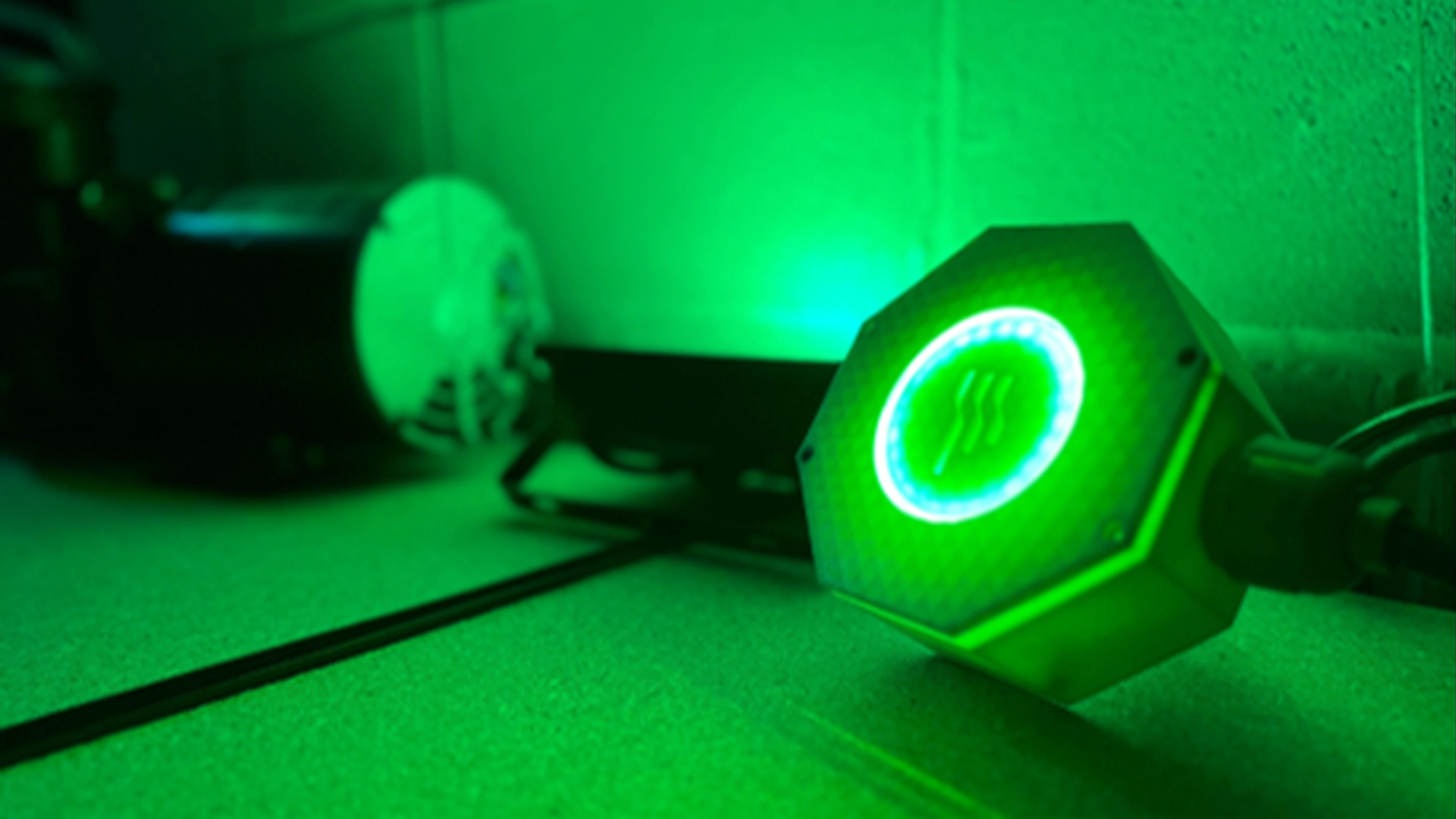
Mechanical design had to survive contact with the whole system.
The project progressed from CAD and component design into printed hardware, internal integration, and assembled prototype testing.
Confidential implementation details are intentionally omitted; the page focuses on the mechanical-development workflow supported by the source material.
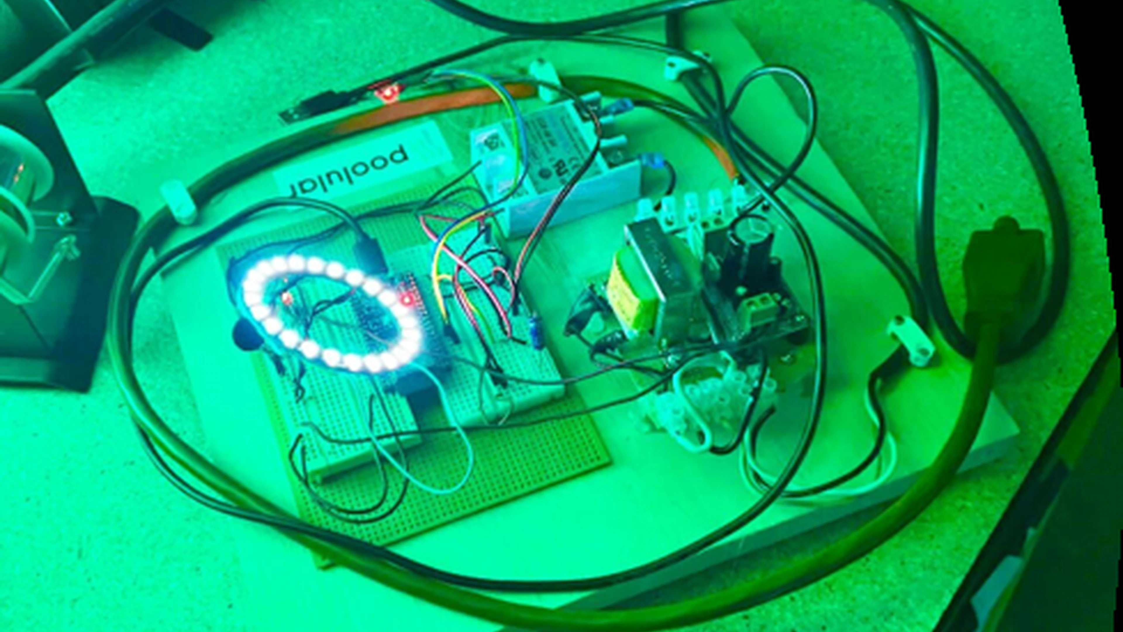
Start with the complete electromechanical system.
The controller housing had to work with electronics, sensors, routing, access, and assembly—not simply look finished.
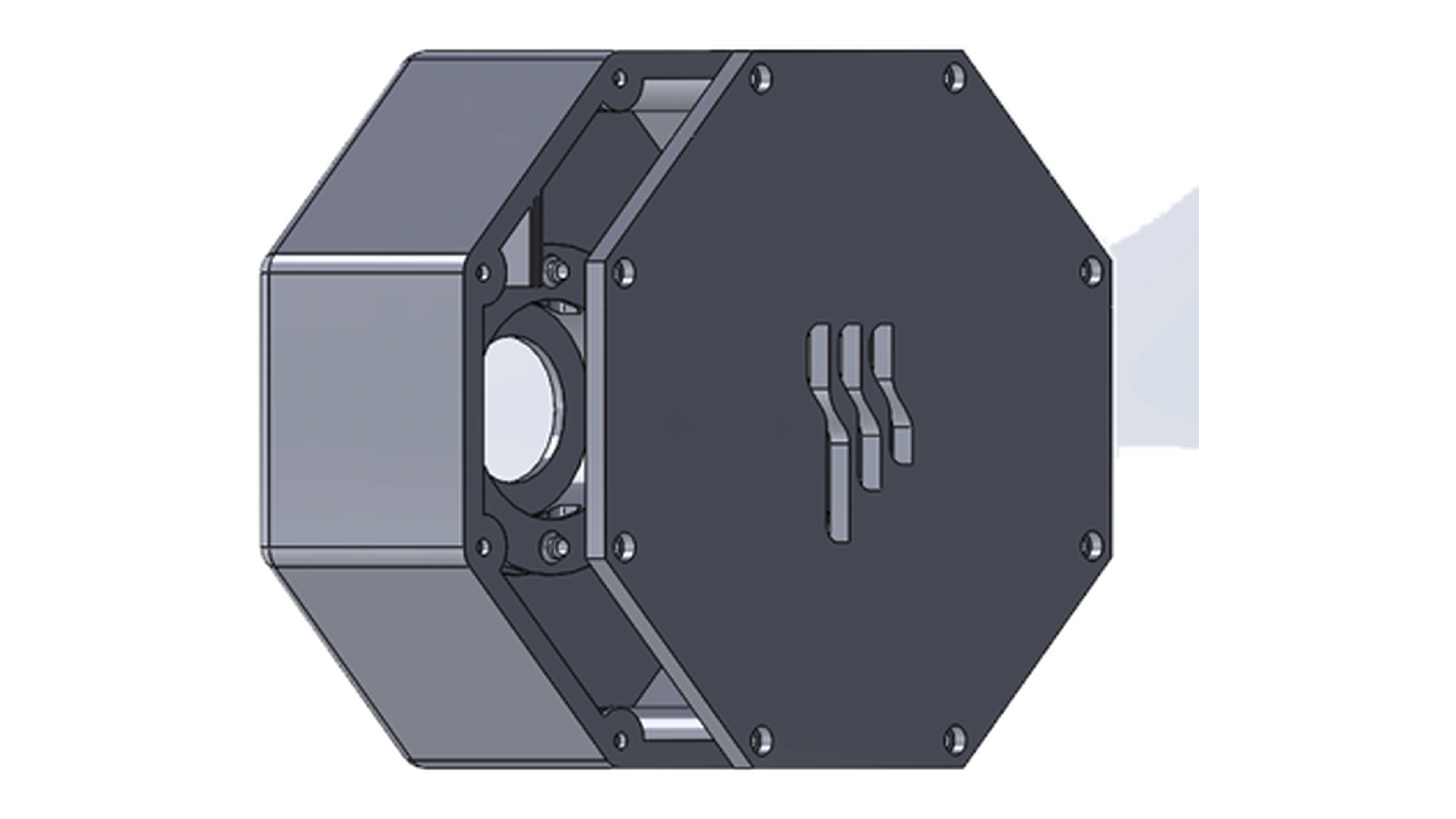
Define the enclosure and interfaces.
The housing CAD establishes the enclosure geometry and interfaces needed to package the system and support prototype assembly.
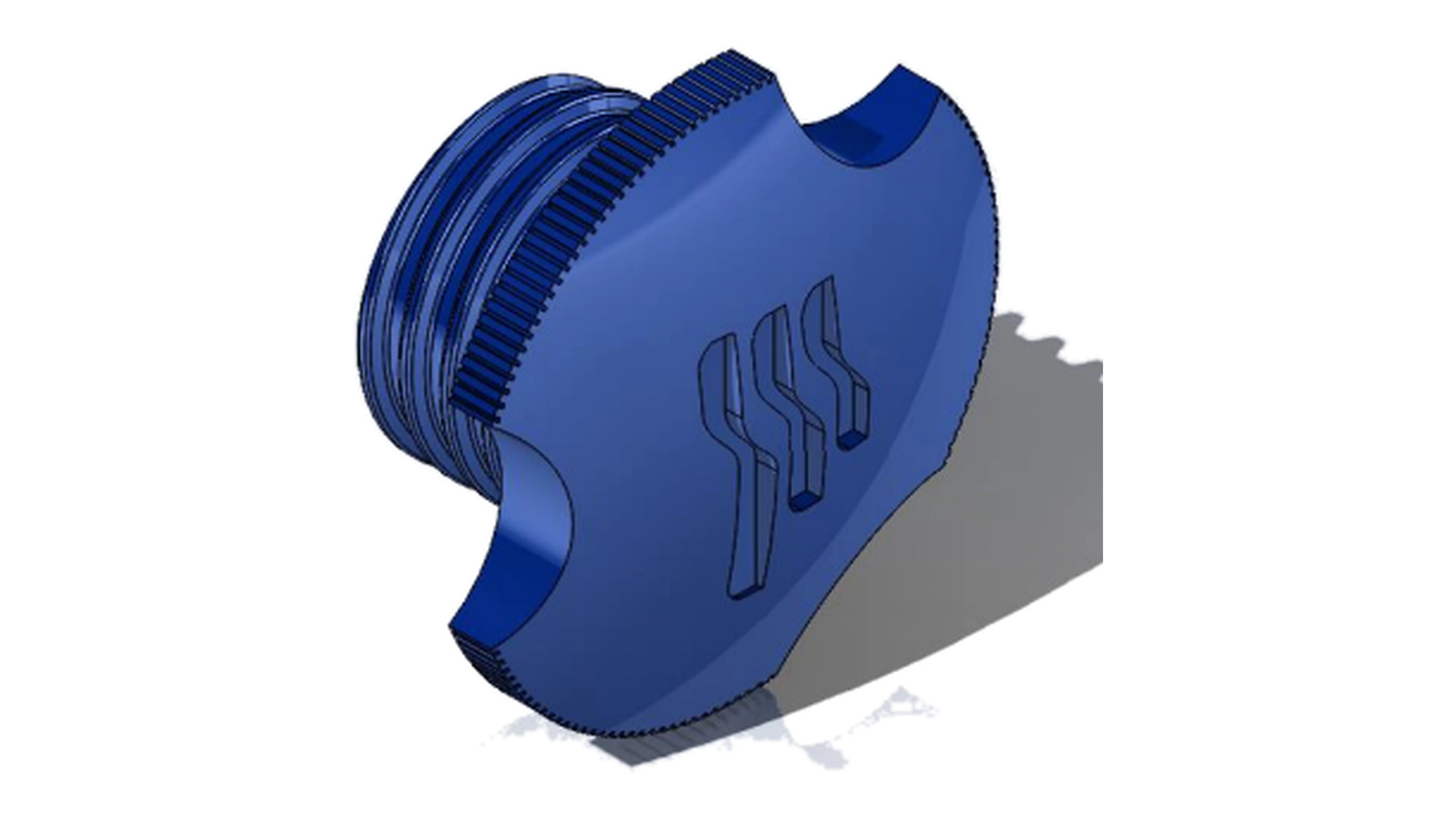
Develop supporting mechanical geometry.
Supporting component geometry was developed alongside the main housing so the internal system could be packaged and assembled coherently.
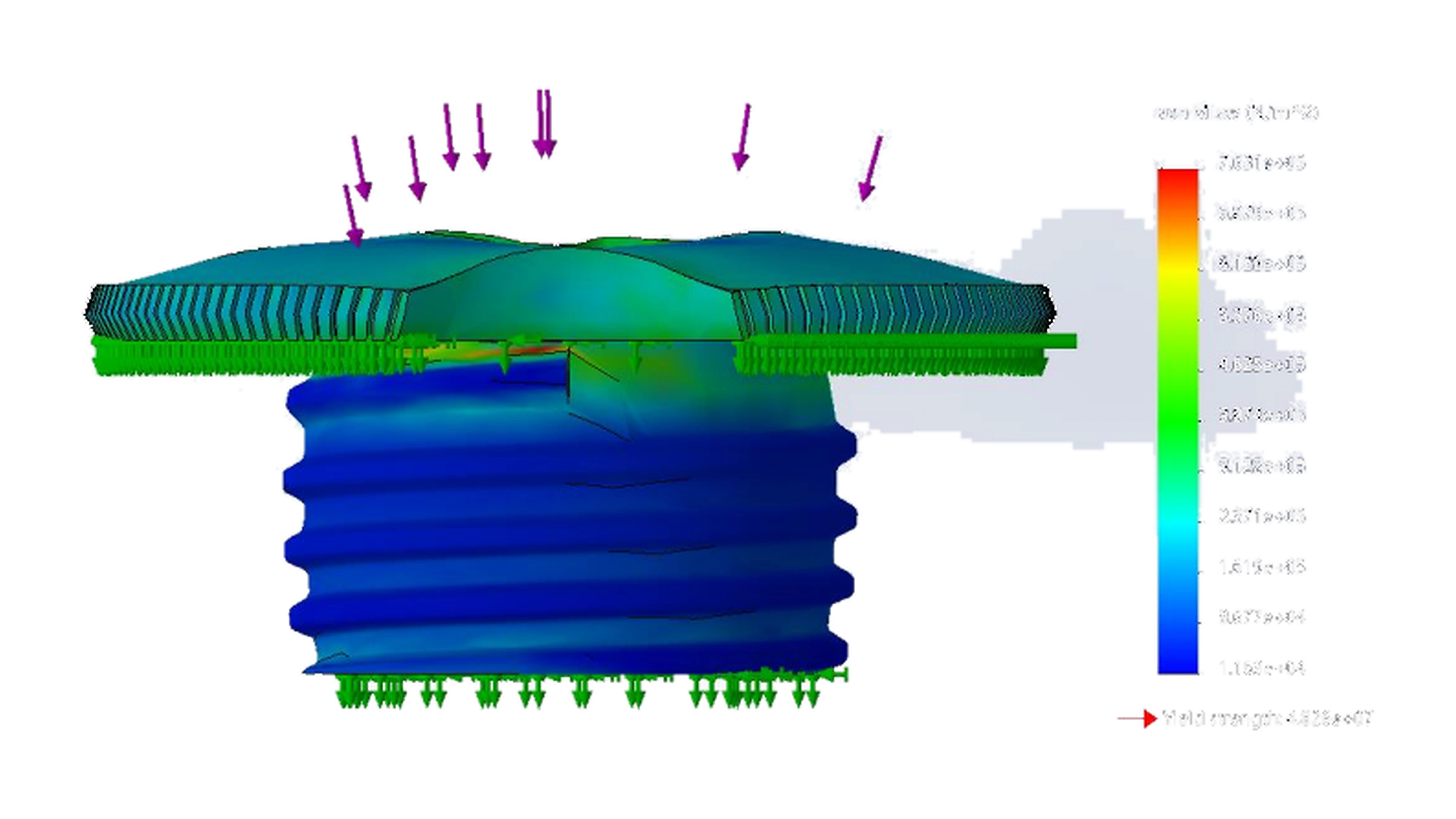
Review the component under a static load case.
The source material includes a static simulation result used to examine the mechanical response of the designed component.
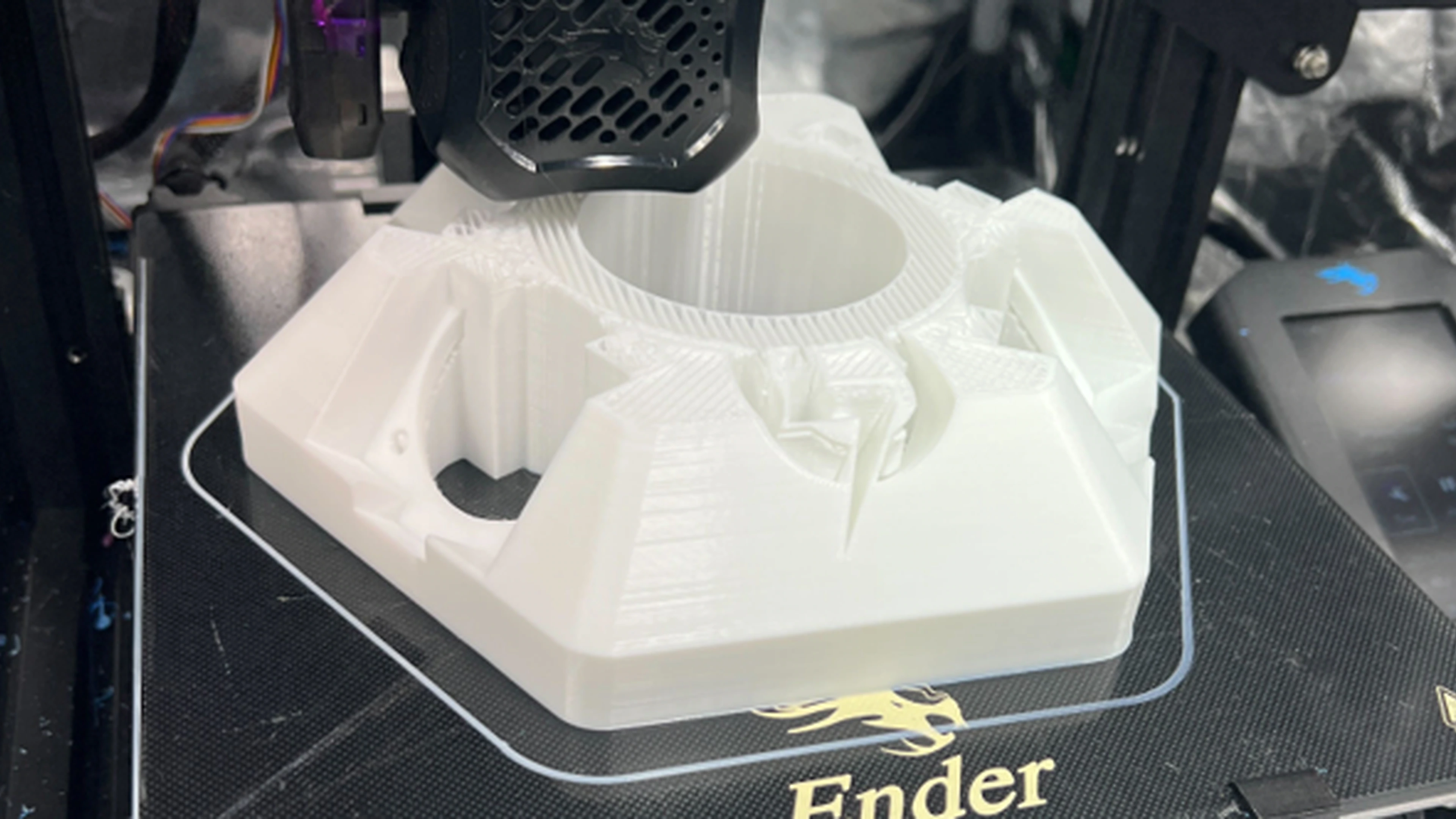
Print the housing.
FDM hardware brought the enclosure into the physical world so fit, routing, access, and assembly issues could be evaluated directly.
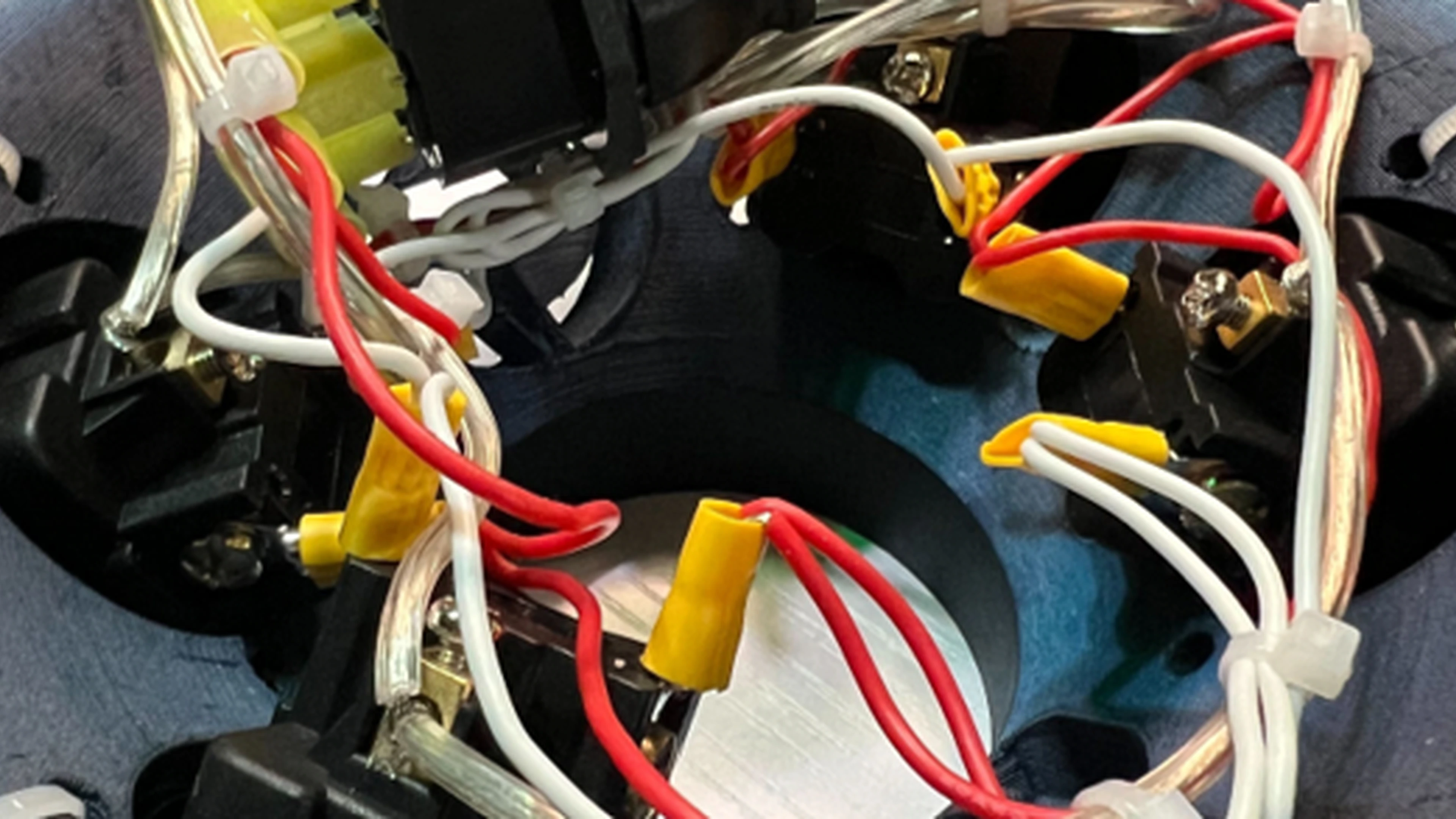
Bring electrical and mechanical hardware together.
The prototype was integrated with control electronics and wiring. Fixture-assisted assembly supported the mechanical/electrical integration effort.
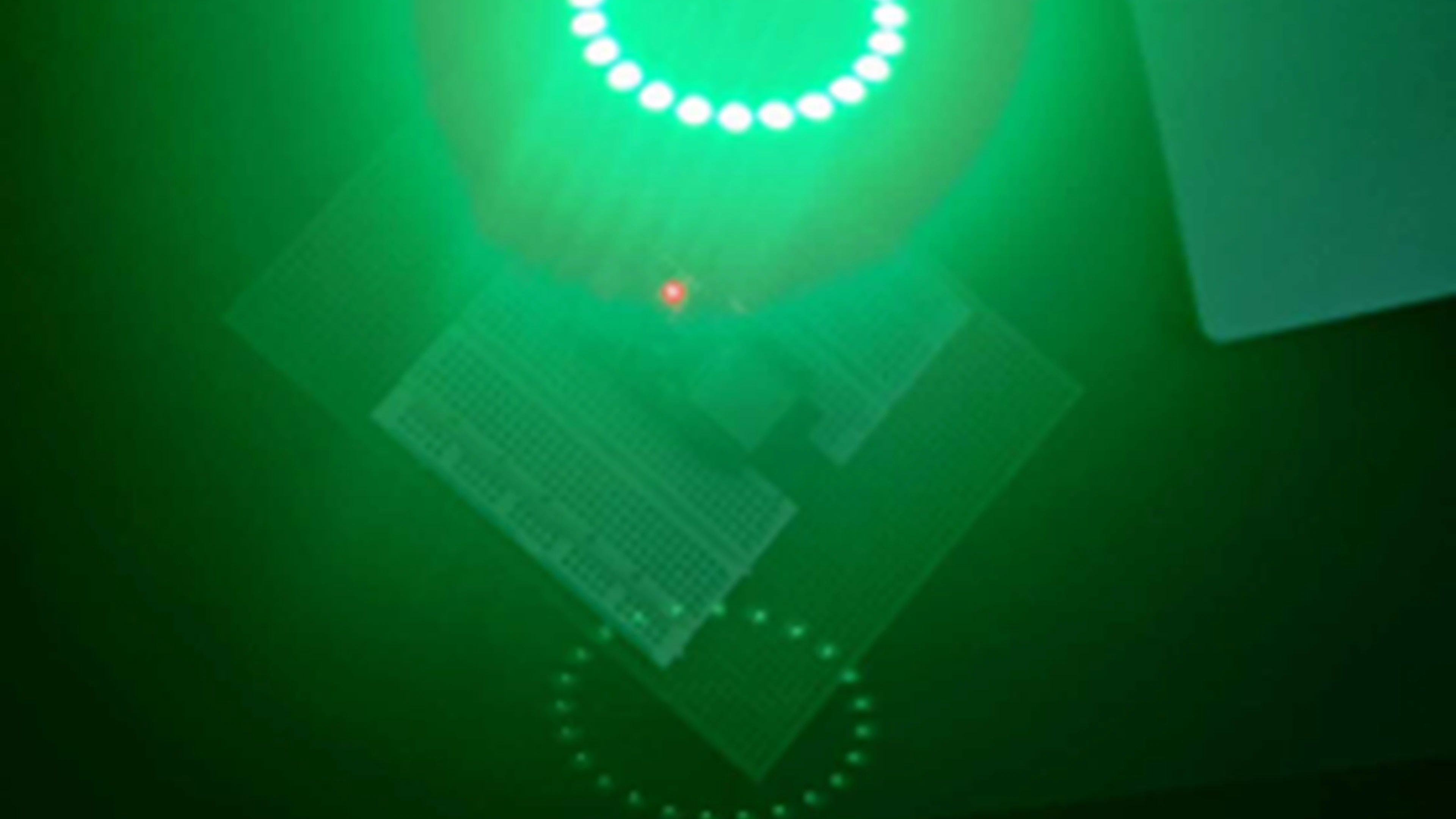
Evaluate the assembled controller.
The assembled prototype was taken through functional testing and design-iteration cycles with cross-functional partners.
Overall system performance improvement
The portfolio attributes the contribution to fixture-assisted assembly, system integration, prototype testing, and design iteration.
See the environment,
not a collage.
The source Drive folder also includes a short prototype video, embedded directly.