Lightweight Bicycle Fender
A complete scan-to-CAD and simulation-led redesign: reverse engineering, boundary conditions, individual static-analysis outputs, topology optimization, manufacturable rebuild, mounting design, and additive-manufacturing preparation.
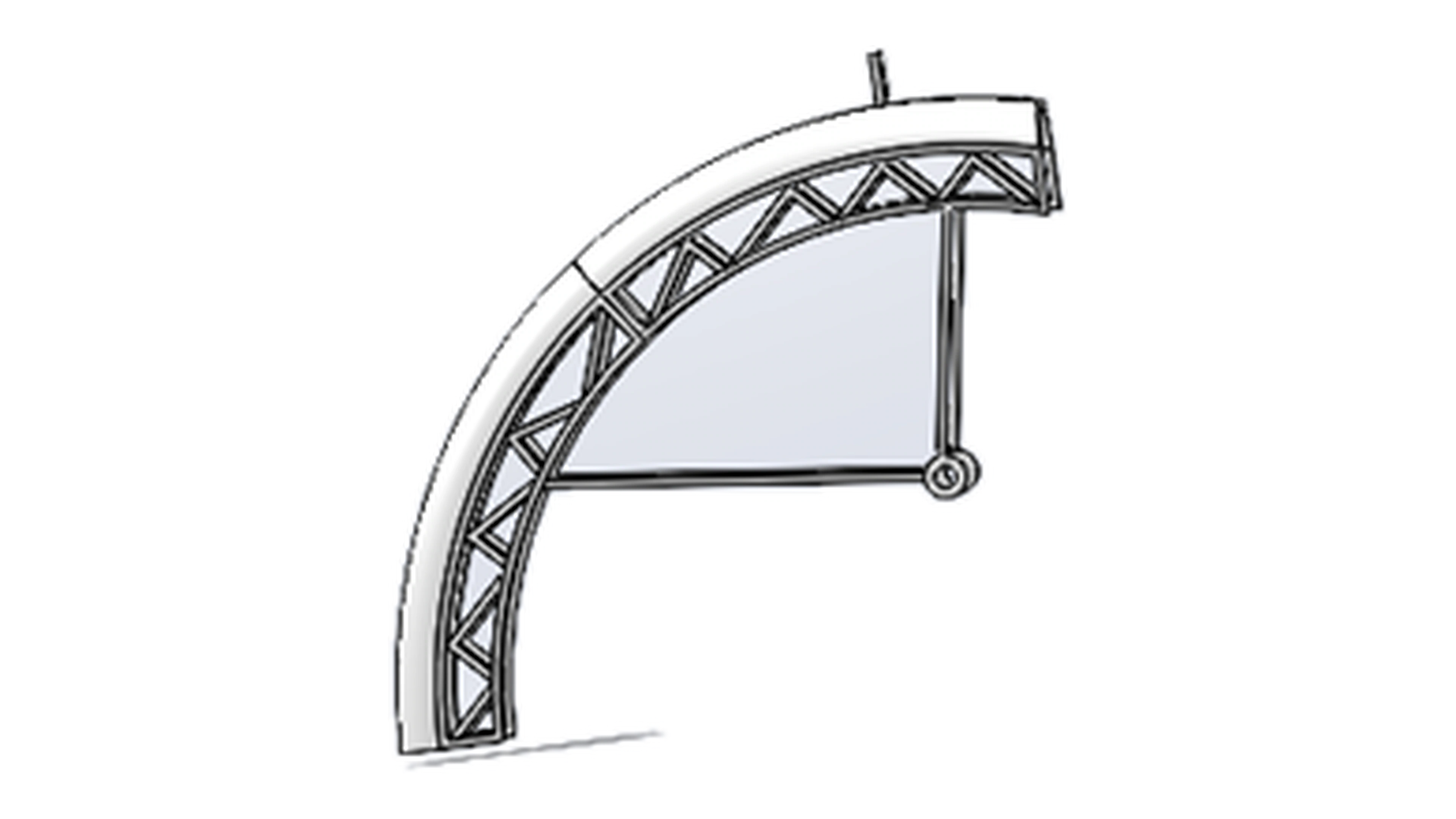
The final part is only the last step.
This case study now exposes the engineering sequence in detail instead of compressing the process into a few combined images.
The workflow starts with scan data, builds an accurate reference, defines the simulation, separates displacement/strain/stress outputs, interprets topology optimization, rebuilds geometry, resolves mounting, and prepares the part for printing.
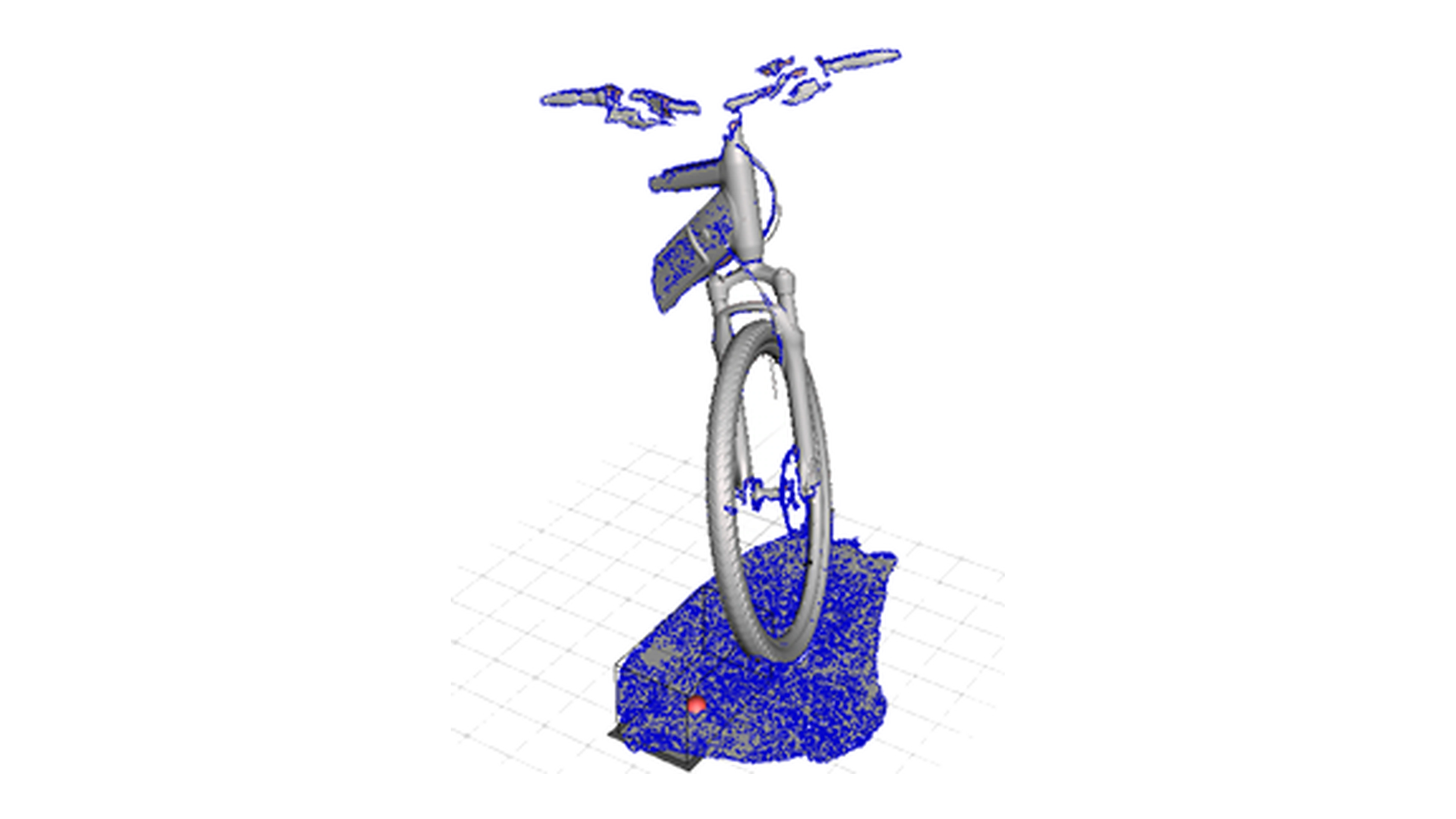
3D scan the bicycle and wheel geometry.
The workflow begins with physical geometry rather than a clean CAD model. The complete bicycle scan establishes the real reference condition.
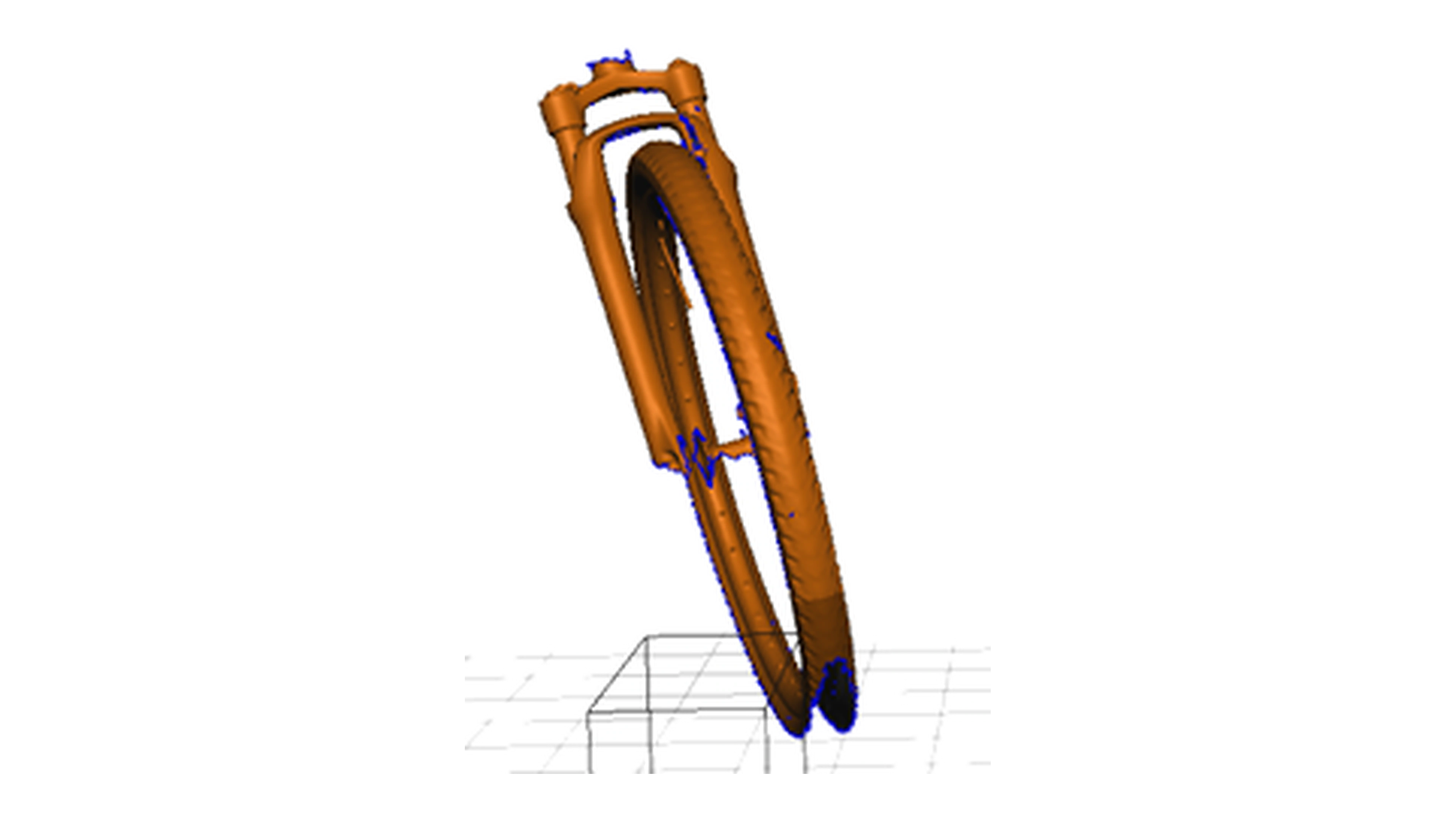
Isolate the fork and wheel region.
The scan was cleaned and simplified so the critical fork and wheel geometry could be used as a design reference instead of carrying unnecessary mesh noise.
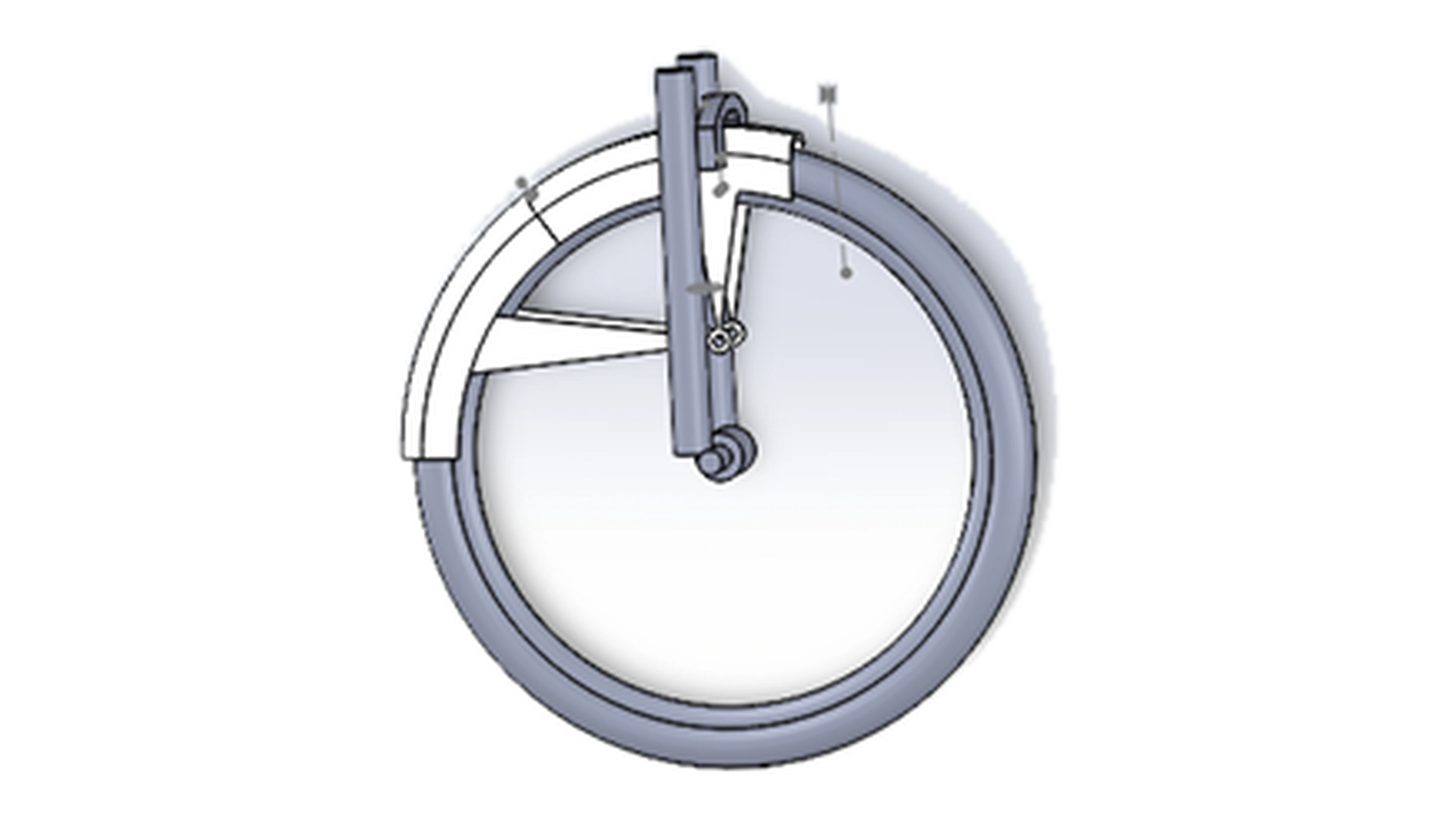
Create reference CAD geometry.
The reconstructed wheel and fork establish the geometry needed to model the fender and its mounting relationship.
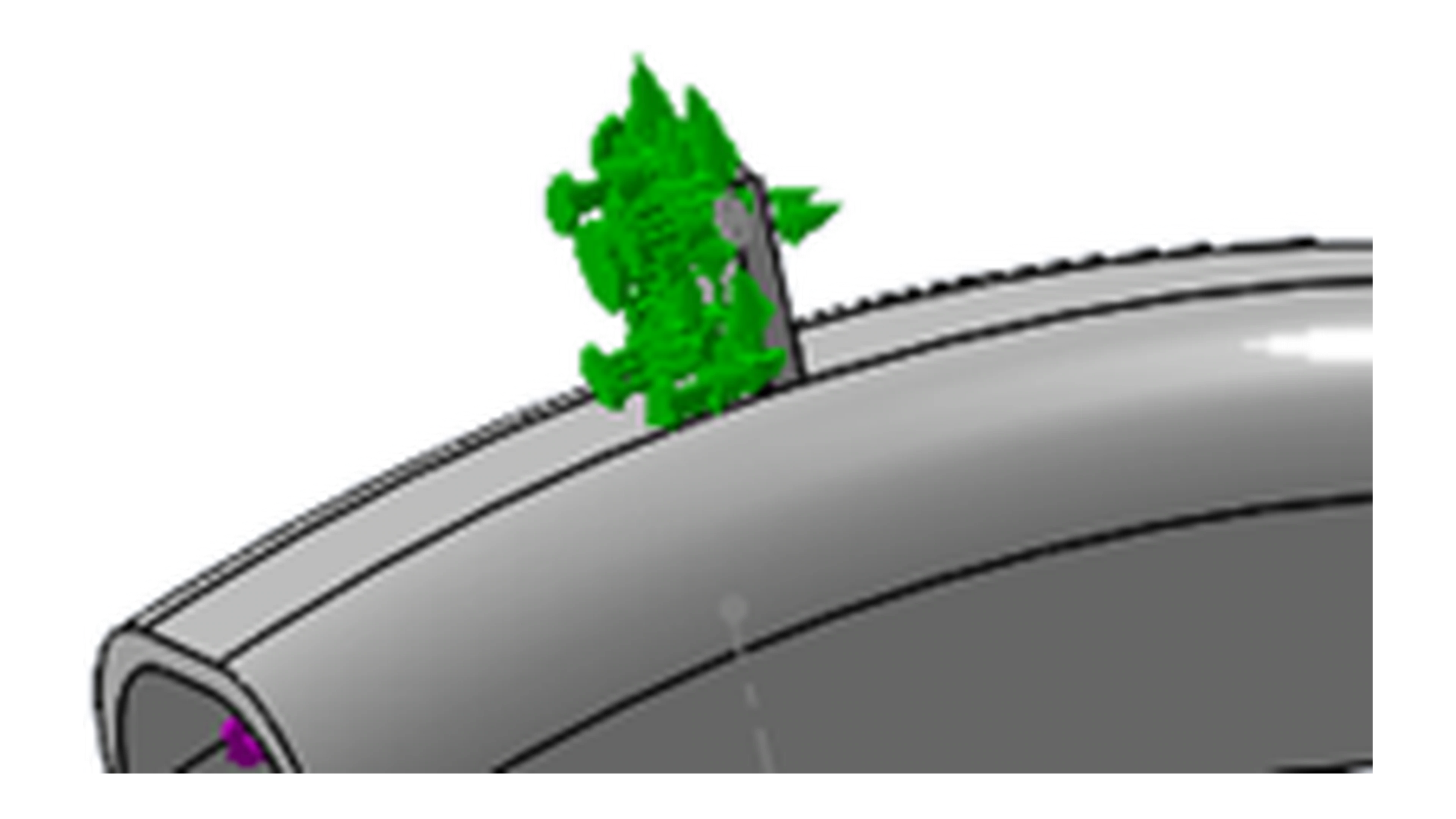
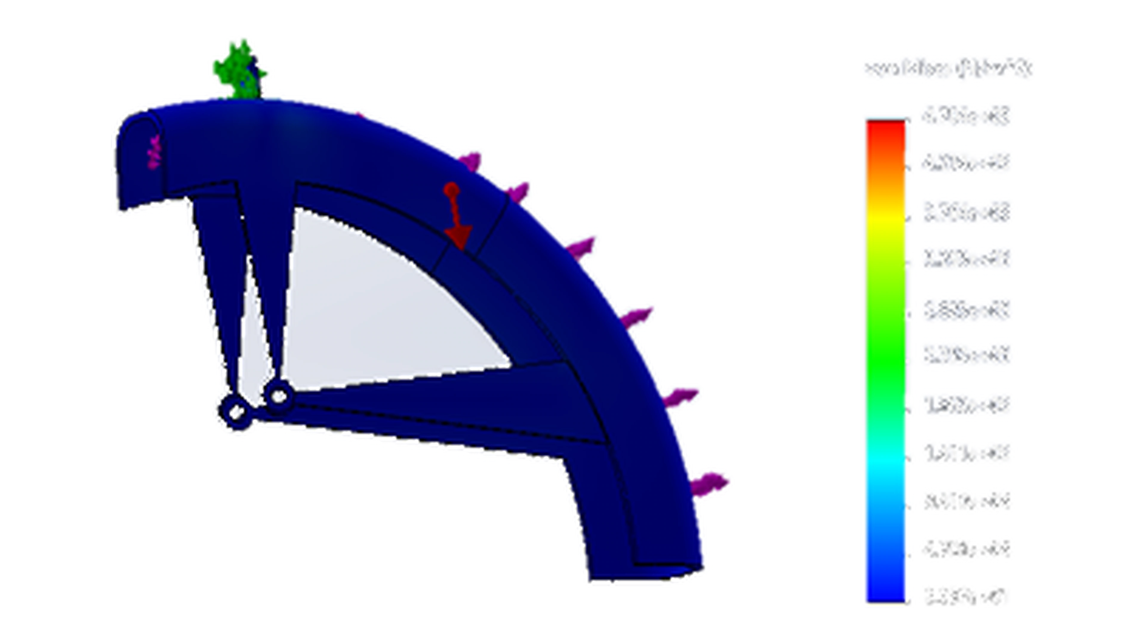
Define the restraint condition.
The static study starts by constraining the model at the intended support location.
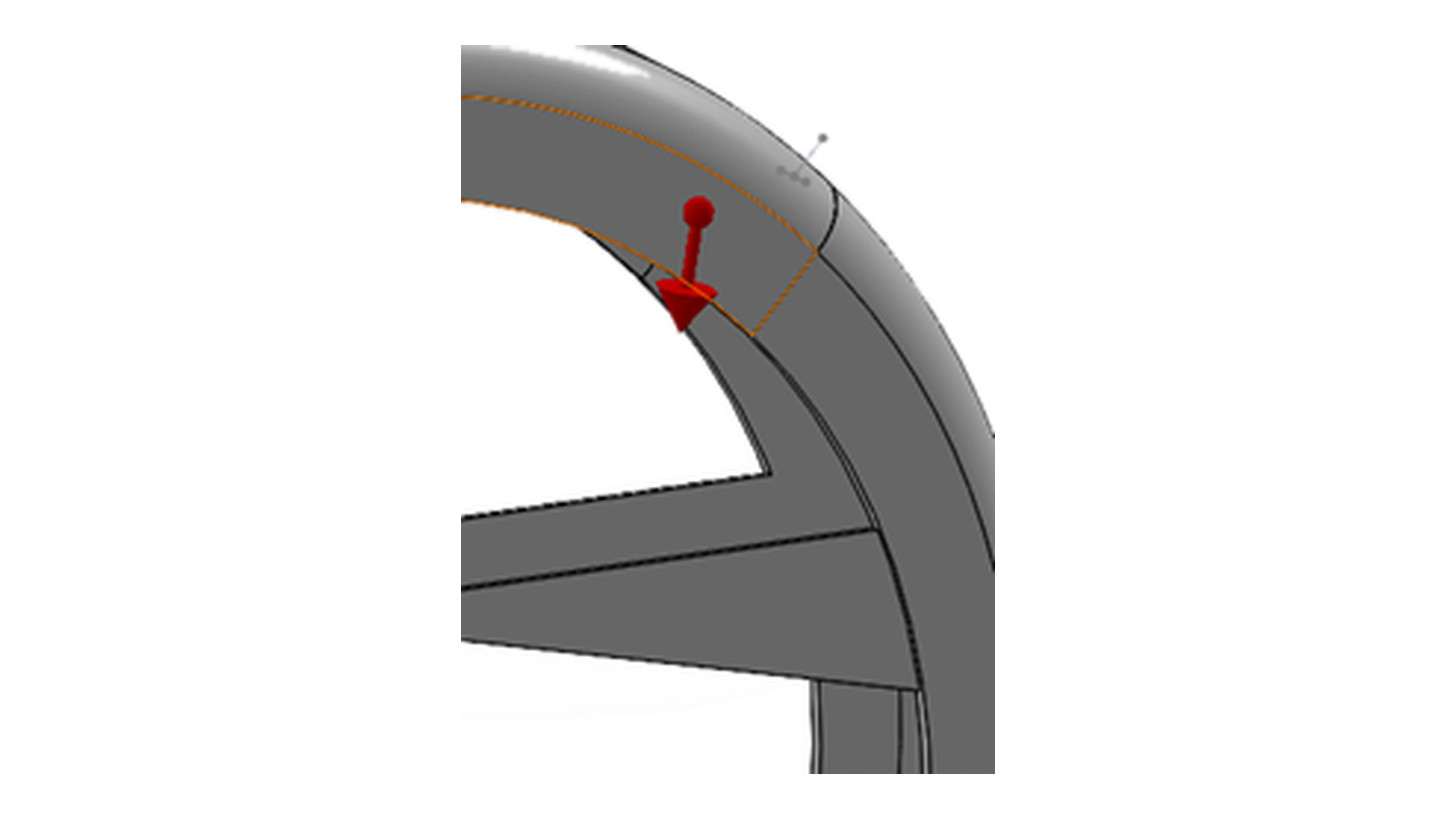
Apply the design load.
The loading condition is applied to the fender model before solving for structural response.
One result.
One image.
The simulation outputs are shown separately at full scale. The previous combined white-background collage is gone.
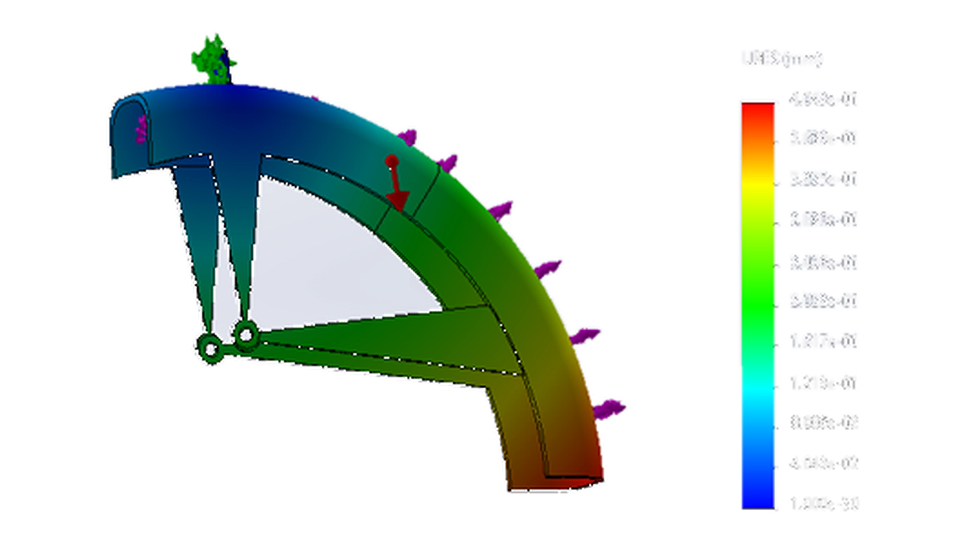
Displacement
SolidWorks Simulation displacement result shown as its own figure, with the original color scale retained.
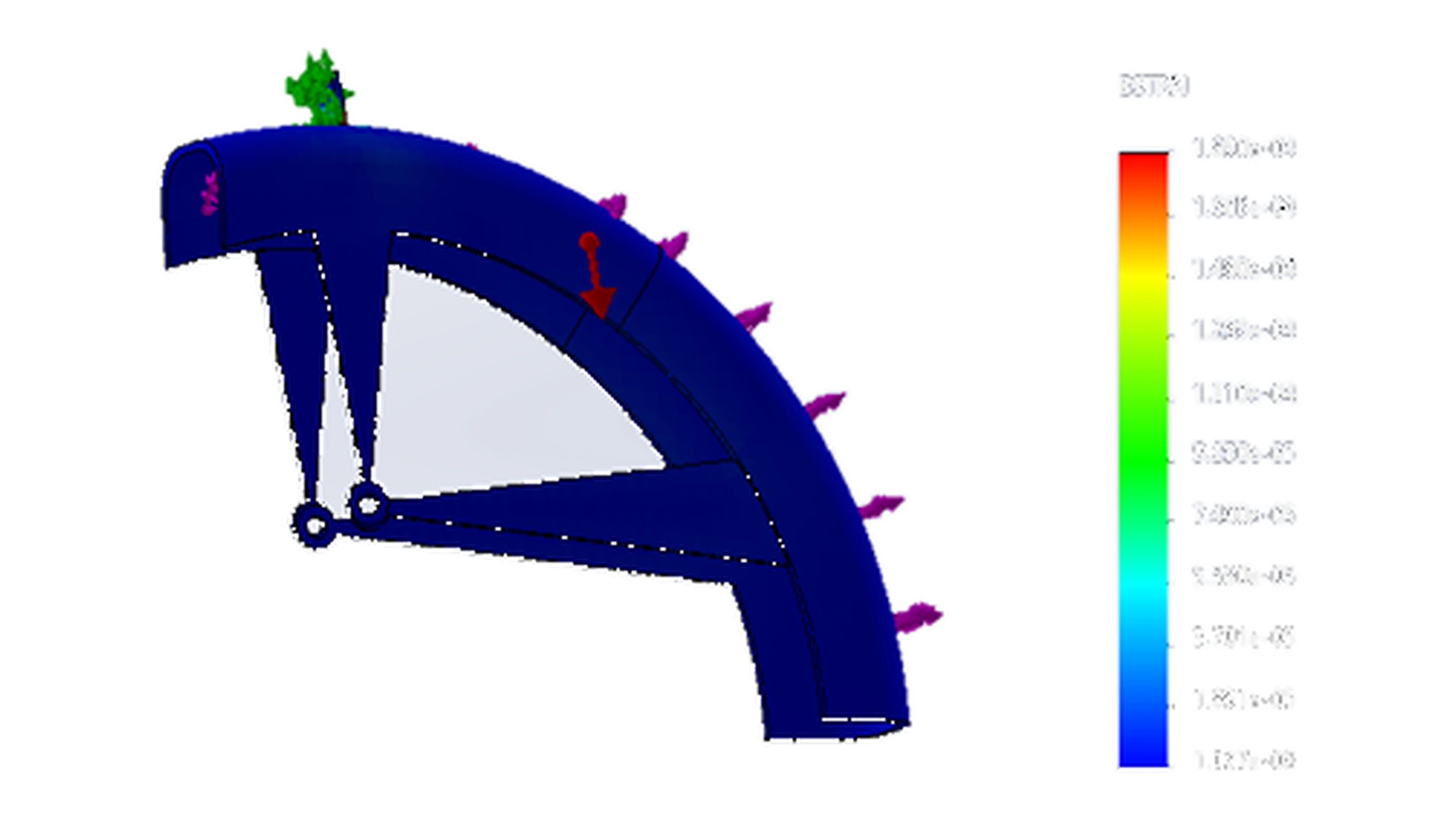
Strain
Static-study strain output shown separately rather than grouped into a collage.
von Mises stress
Stress output shown as a standalone figure so the load path and stress distribution are easier to inspect.
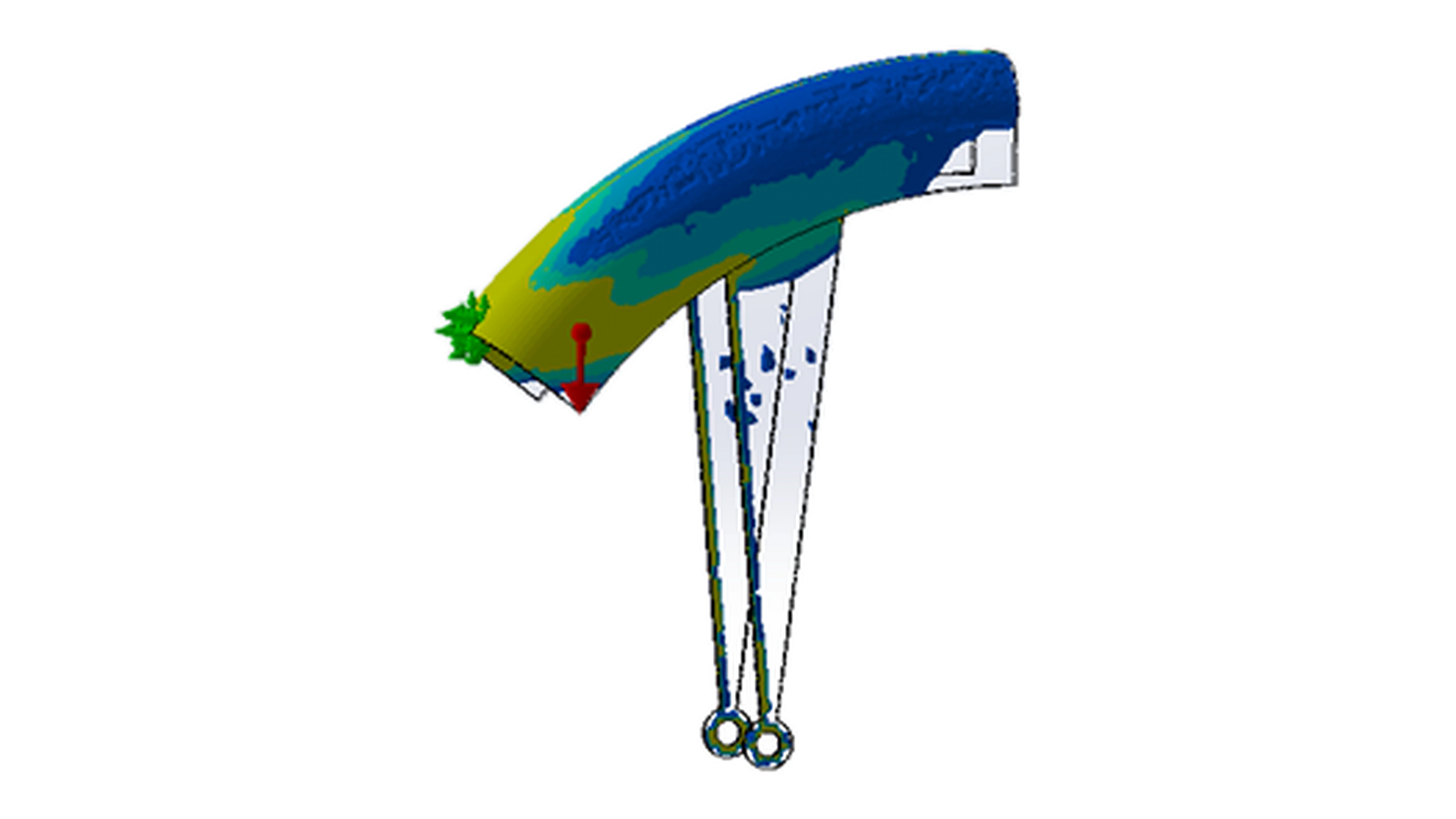
Use the structural response to guide material removal.
The topology study identifies where material contributes to the load path and where mass can potentially be removed.

Review the optimized structural direction.
The topology result is treated as engineering information—not as final manufacturable geometry.
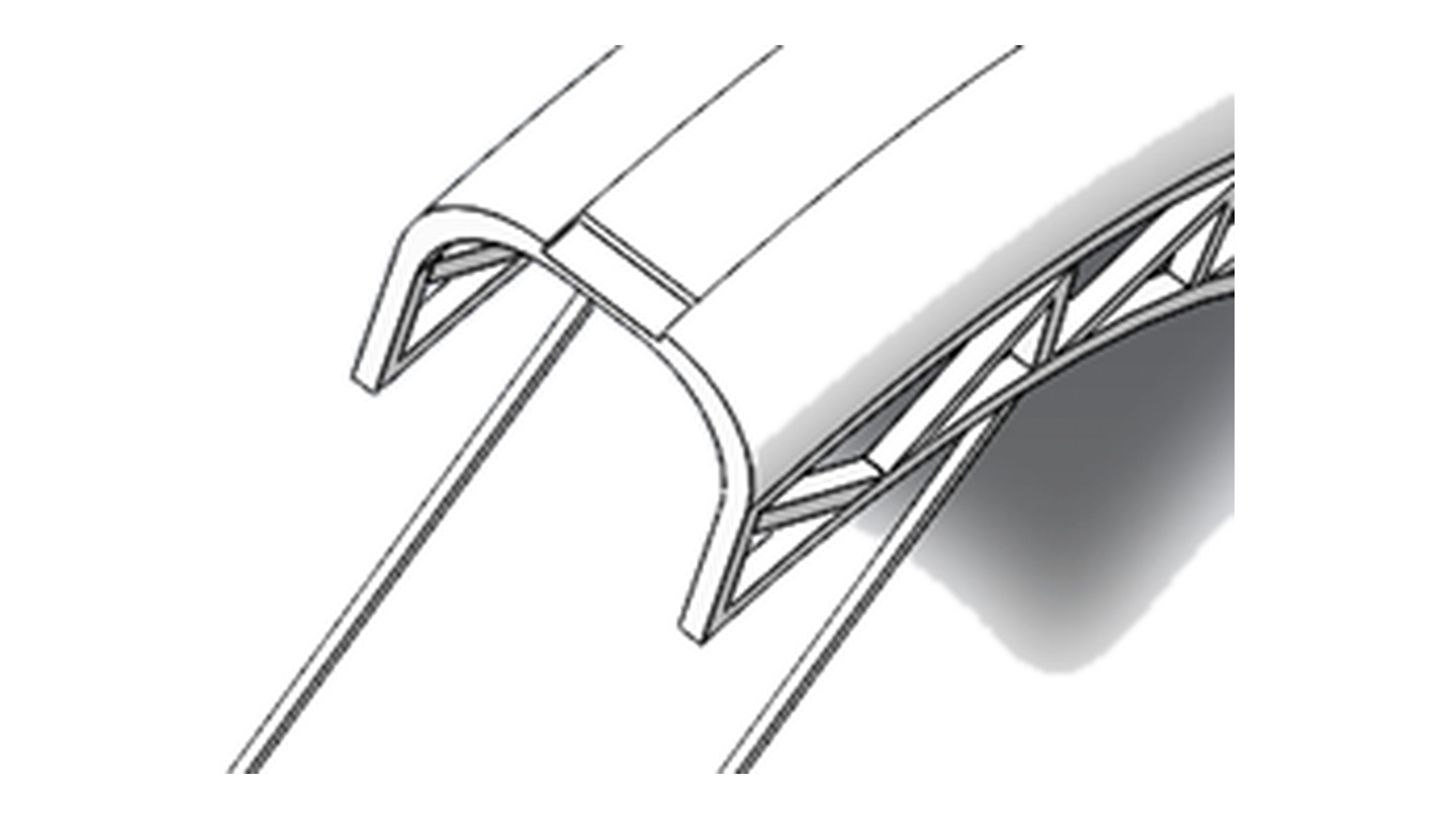
Translate optimization into printable CAD.
The final geometry was rebuilt to retain the mounting relationship while turning topology information into a manufacturable structure.
Refine local geometry.
Local fender and brace geometry was refined after the major structural layout was established.
Resolve the fork attachment.
The mounting relationship between the fender support and bicycle fork was developed as a separate interface problem.
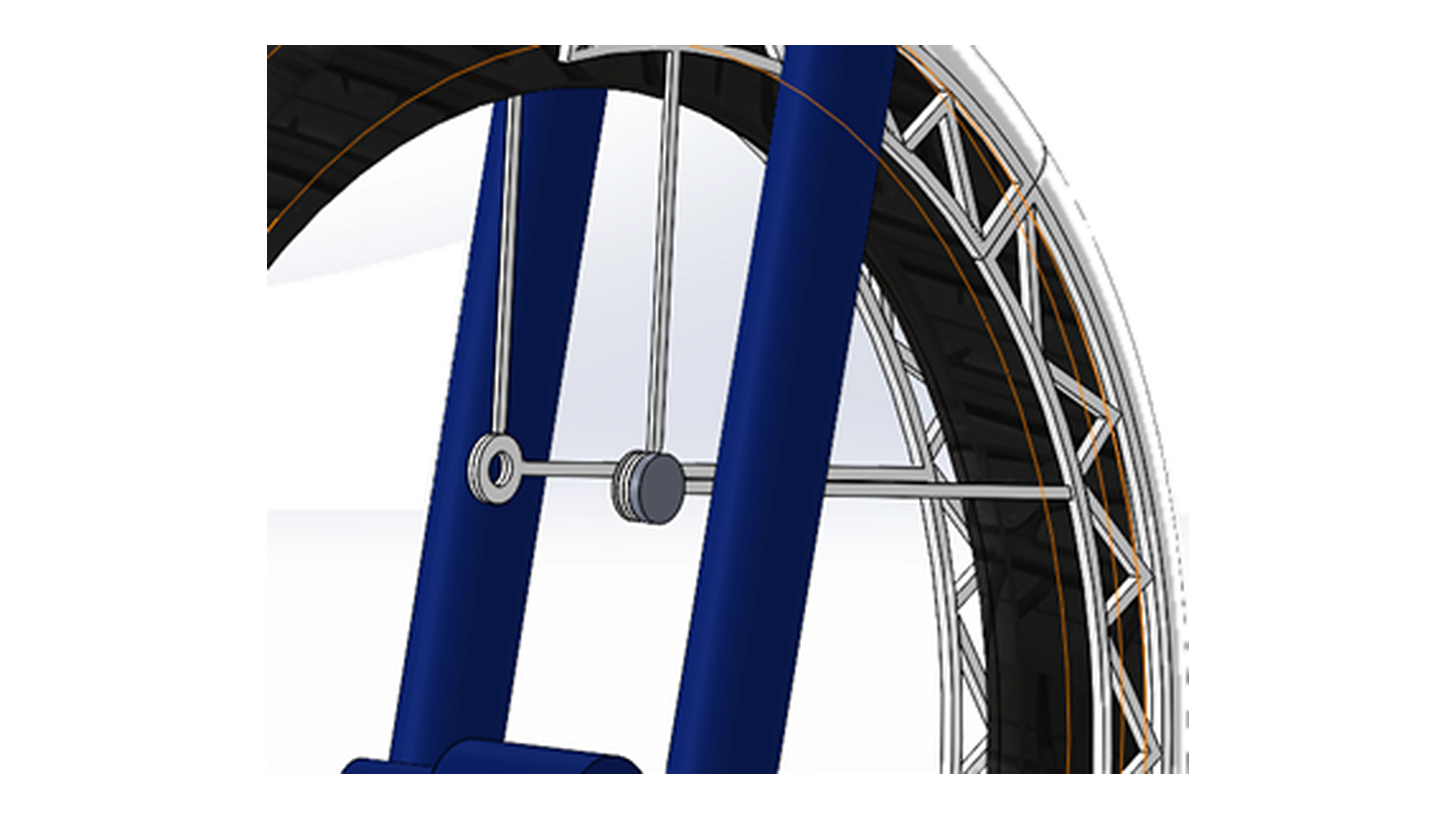
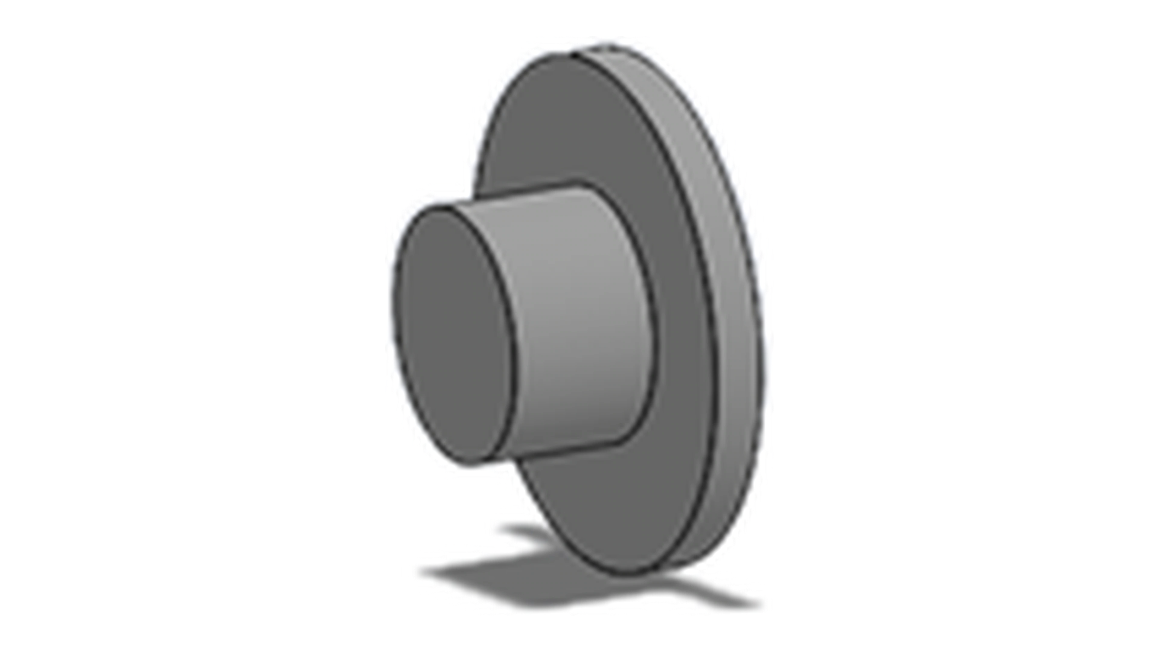
Develop the attachment hardware.
The source folder contains separate hardware geometry used in the attachment system.
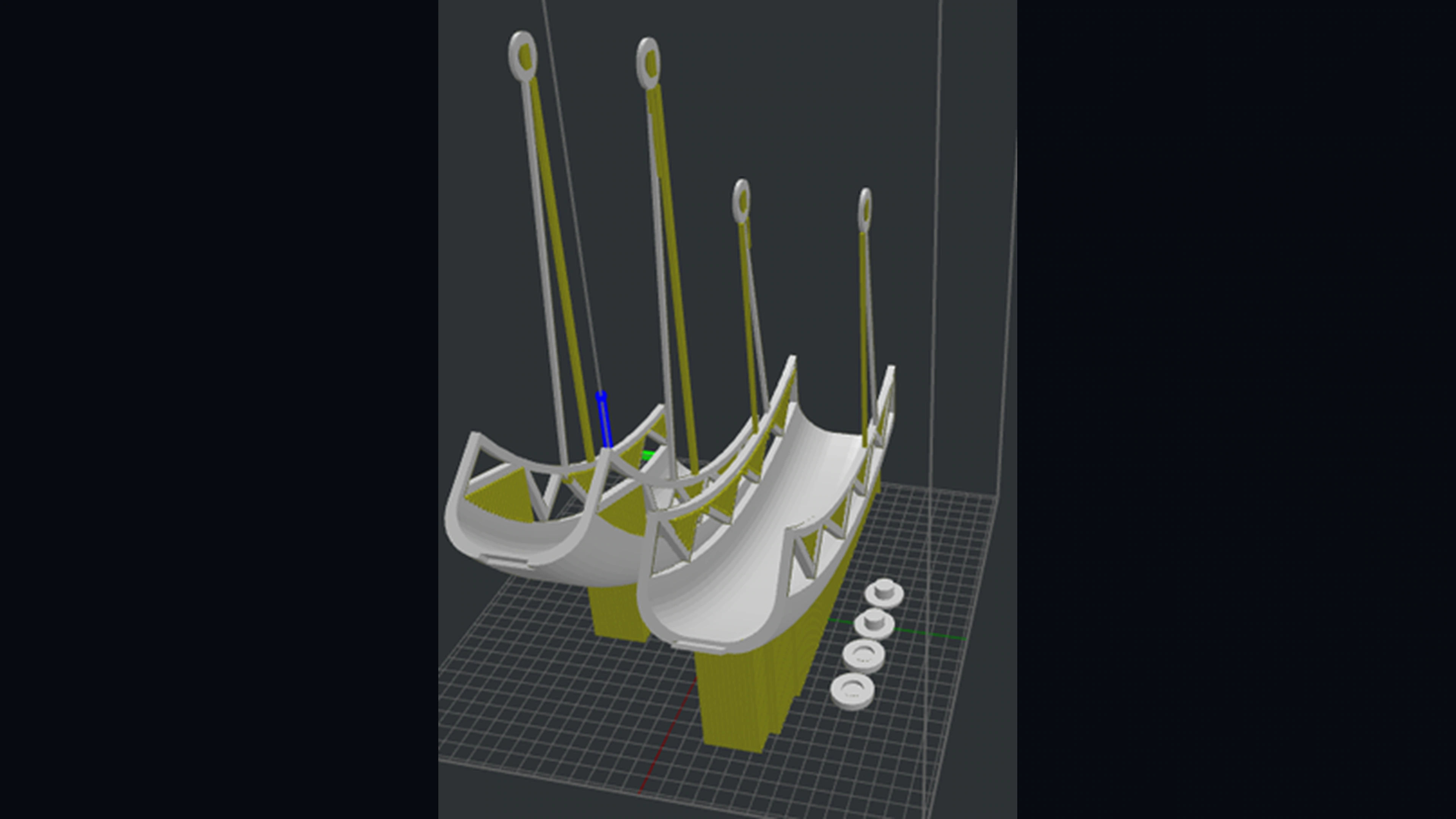
Orient the design for additive manufacturing.
The design was positioned for printing to balance structural direction, support material, and manufacturability.
Weight reduction: 1.40 lb → 0.52 lb
The final design preserved mounting geometry and wheel clearance while converting the topology result into printable CAD geometry.